APUS I2C/ SPI/ GPIO Host Adapter
Part No.: MPTP-I2C/SPI-APUS
It designed for controlling any test system incorporating I2C, SPI or general purpose IOs.
Product Description
APUS Overview
APUS is an interface adapter designed for controlling any test system incorporating I2C, SPI or general purpose IOs (GPIO). Today, the usage of these protocols is extremely widespread, including electronics for telecommunications, portable electronics and medical electronics.
APUS is simply connected to the system under test using one or more of the available interfaces. APUS accepts USB commands from the host PC and then implements the necessary bus protocol for I2C bus, SPI bus or GPIO bus as required. The connection back to the host PC is via a standard USB cable, which provides all power requirements of APUS.
Host PC
The host PC includes the necessary driver and DLL to implement the high level commands so that the user can rapidly develop his/her own custom applications.
Typical applications are written in C/C++ or Visual C++. Users have the choice of developing GUI-style control applications or non-Windows-batch-style control - depending on the requirements.
APUS comes with a rich set of example applications and documentations, making custom applications an extremely simple process even for those with little programming knowledge.
I2C Bus Interface:
The I2C bus interface contains both master I2C and slave I2C capability with line rates of 10kBit/s, 100kBit/s, 200kBit/s, 400kBit/s, 1MBit/s, 3MBit/s and 6MBit/s.
The interface supports wait-stating through clock stretching by the slave.Back-to-back I2C commands are supported using repeated start.
A jumper setting allows the interface to have no pull-up resistors, on-board 1.5kOhm pull-up resistors to 5V or on-board 1.5kOhm pull-up resistors to 3.3V.
SPI Bus Interface
The SPI bus interface contains both SPI master and SPI slave capability with full duplex (simultaneous read/write) at line rates of 10kBit/s, 100kBit/s, 200kBit/s, 400kBit/s, 1MBit/s, 3MBit/s, 6MBit/s and 12MBit/s.The interface has configurable clock polarity (CPOL) and clock phase (CPHA). The SPI interface can interface up to 17 master or slave devices by using some of the GPIO pins as chip selects. Chip selects may be active low or active high.
GPIO Bus Interface
The GPIO bus interface is split across two ports.
-
Port A: provides 16 advanced GPIO bits. Each bit can be individually configured as digital IO, PWM, continuous pulsed, single pulsed or interrupt input. Pulse widths, duty cycle and pulse sense are also programmable. The lower 2 bits of the Port A GPIOs have a low-pass filter which can be selected via a jumper and can be used with PWM to turn the GPIO into an analog output.
-
Port B: provides a further 16 digital IOs.
Analog
The analog interface provides 4 analog inputs which can be sampled with 8 bit resolution.
API
The API (Application Programming Interface) is designed for easy use in creating custom applications incorporating simple high level commands. Some examples of functions which can be called are shown here:
| Nano_GetEvents() | Nano_SPIMasterSetFrequency() |
| Nano_SPIMasterReadWrite() | |
| Nano_GPIOASetContinuousMode() | Nano_SPIMasterWrite() |
| Nano_GPIOASetPulseMode() | Nano_SPIMasterRead() |
| Nano_GPIOASetPWMMode() | Nano_SPISlaveBufferWrite() |
| Nano_GPIOASetDigitalOutputMode() | Nano_SPISlaveBufferRead() |
| Nano_GPIOAGetDigitalInput() | Nano_SPISlaveArm() |
| Nano_GPIOAGetInterruptInput() | |
| Nano_GPIOBWrite() | Nano_I2CMasterSetFrequency() |
| Nano_GPIOBRead() | Nano_I2CMasterScanConnectedDevices() |
| Nano_GPIOBSingleBitWrite() | Nano_I2CMasterWrite() |
| Nano_GPIOBSingleBitRead() | Nano_I2CMasterRead() |
| Nano_I2CMasterWriteRead() | |
| Nano_ADCRead() | Nano_I2CSlaveArm() |
Examples

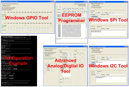
In order to help users develop custom applications, a collection of GUI and non-Windows style applications have been developed to show how to link to the API.
The application examples are written in C/C++ and Visual C++ on Windows 2000/XP/Vista, Linux or Mac OS X. The example applications can be run before you purchase the product to get a feel for what APUS can do for you.
The application examples are well documented.